An LT cable fault can begin with the wrong conductor size, an overloaded route, a damaged sheath or a poorly crimped lug. By following a controlled test sequence, checking the installation conditions and matching the cable to its records, you can separate a failed cable from a termination, protection or supply problem before replacing sound materials.
Key takeaways
- Apply lockout/tagout and prove the circuit dead before inspection.
- Use insulation resistance, continuity and phase-identification tests to locate faults.
- Match cable size to load, route, voltage rating and installation conditions.
- Record the cable specification, batch details, test results and handover approvals.
Start with isolation, inspection and a controlled fault sequence
Isolate the installation before touching the cable. A qualified electrician should identify every supply and possible backfeed, open the correct disconnectors, apply lockout/tagout, and prove the circuit dead with a suitably rated voltage tester. Discharge stored energy and prevent anyone from re-energising it.
- Record the fault: tripping time, affected circuit, load condition, smell, noise, smoke, and any visible heating or arcing.
- Inspect the breaker, busbar, cable route, glands, joints, lugs, terminations, and load without disturbing them. Look for loose hardware, burnt insulation, water ingress, crushed sheath, sharp-bend damage, and incorrect phase or neutral connections.
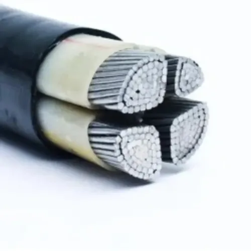
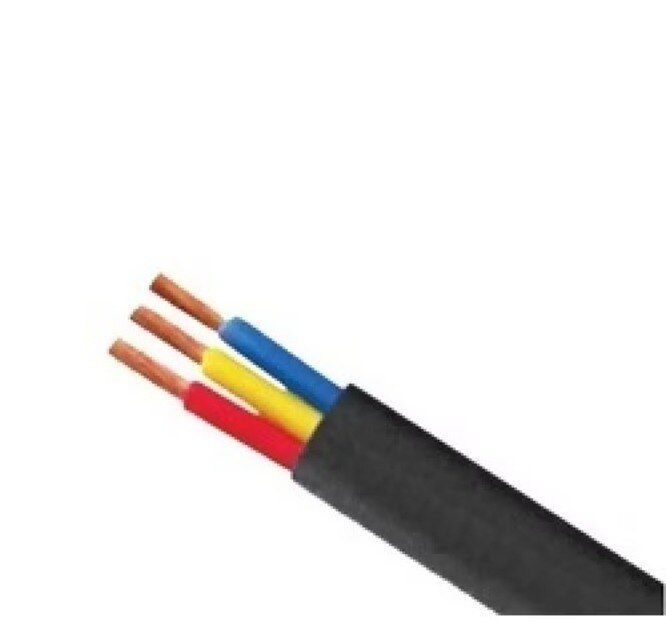
- Confirm the cable identity before testing: system voltage, conductor material, insulation, armour, core count, size, and installation method. A 1.1 kV XLPE cable is checked against IS 7098 (Part 1); a PVC-insulated power cable is covered by IS 1554 (Part 1).
- Follow a controlled fault sequence: check the upstream supply and breaker, then cable continuity and phase identification, protective-conductor or armour continuity, insulation resistance, sheath condition, and finally the termination and load.
- Use an appropriate megohmmeter only after isolating the cable, disconnecting sensitive equipment, preparing and securing both ends, and confirming safe discharge afterward.
Do not treat a megger result as a complete diagnosis. It cannot prove correct phasing, sound lugs, mechanical integrity, or a healthy load. Stop and escalate Polycab LT cable problems when testing reveals damaged insulation, repeated overheating, or uncertain isolation.
Use the right instruments to locate the actual failure
A qualified electrician should test from the source towards the load, isolating and locking out each section before opening it. Never use a continuity meter or megohmmeter on an energised circuit; disconnect sensitive equipment before insulation testing.
- Measure voltage phase-to-phase and phase-to-neutral at the upstream supply, busbar, breaker line side and breaker load side. A missing or unstable reading before the cable points to the supply or busbar; a difference across the breaker points to the breaker.
- Verify phase sequence, polarity and neutral identification with a phase-sequence meter and approved voltage tester. A swapped phase or neutral can imitate cable failure.
- Check conductor, protective-conductor and armour continuity with a low-resistance ohmmeter. Open or unusually high resistance at one core suggests a broken conductor, lug, gland bond or joint.
- Test insulation resistance between cores and from each core to earth with an appropriate megohmmeter. Test the cable in sections, with both ends disconnected; a failed section localises the fault, but a pass does not prove correct phasing or sound terminations.
- Inspect lugs, glands, joints and breaker terminals, then compare crimping, aluminium oxide removal, connector type and tightening torque with the component manufacturer’s instructions.
| Source indicated | Confirming check | Typical clue |
|---|---|---|
| Cable or sheath | Sectional megohmmeter and visual inspection | Low insulation resistance or sheath damage away from ends |
| Termination or joint | Low-resistance test and thermal scan under controlled load | Hot lug, loose gland, poor crimp or phase imbalance |
| Breaker or busbar | Voltage on both sides and torque inspection | Correct incoming voltage but absent or unstable outgoing voltage |
| Load or upstream supply | Isolate load; measure supply stability | Fault follows the appliance, or supply voltage varies before the breaker |
Check cable selection against load, route and identification details
A cable-selection error follows the design; an installation-workmanship error appears after the specified cable was installed incorrectly. Check the cable’s system voltage, conductor material, insulation, armour, core count and installation method before blaming either one.
A 1.1 kV XLPE cable is normally checked against IS 7098 (Part 1), while a PVC-insulated power cable is checked against IS 1554 (Part 1).
| Check | Selection error | Workmanship error |
|---|---|---|
| Load | Cross-section cannot carry the design current after grouping and mutual-heating derating | Correct cable is overloaded because circuits were added or protection was set incorrectly |
| Voltage | Excessive voltage drop or inadequate short-circuit withstand for the prospective fault current and clearing time | Loose lug, poor crimp, damaged conductor or high-resistance joint creates local heating |
| Route | Insulation, armour, cover, separation or mechanical protection does not suit wet soil, ducts or construction exposure | Cable exceeds its bend radius, suffers sheath damage, or takes in water through an end or gland |
| Identification | Wrong core count, voltage grade, armour or cable type was delivered | Correct cable is connected to the wrong phase, neutral or termination point |
Use this checklist before cutting or replacing the cable:
- Compare the order with the printed marking: construction, voltage grade, conductor class, core identification, armour, drum length, IS reference and batch information.
- Ask a polycab low tension cable supplier or LT cable dealer for the test documents and confirm the cable’s ampacity, voltage-drop calculation and short-circuit rating against protective-device let-through energy.
- Photograph drum impact, water damage, sheath cuts and a short delivered length before installation; record any mismatch immediately.
- Compare the as-laid route with the design for separation, cover, drainable ducts, markers and bend locations. A matching conductor size does not prove that the route is suitable.
Prevent damage during routing, pulling and termination
Use the manufacturer’s maximum pulling tension, an approved pulling eye or stocking, and enough rollers to keep the cable off sharp edges. Pay the drum out in its marked direction; dragging a drum or forcing a tight bend can stretch conductors and damage the sheath without producing an immediate fault.
During routing and termination:
- Keep every bend above the manufacturer’s stated minimum radius, using the pulling radius during installation and the final radius after placement.
- Seal every cable end during storage, transport and work pauses. Water can travel through stranded conductors and later cause low insulation resistance at a termination.
- Repair a cut or damaged sheath with a compatible approved system before installing the gland or joint; never hide the damage underneath.
- Separate loaded circuits as designed, and apply grouping and mutual-heating derating in trays, trenches and ducts. Nearby ducts can still transfer heat.
- Fit correctly sized lugs, prepare conductor surfaces, complete the specified crimp, and tighten terminals to the manufacturer’s torque. A loose lug creates heat and can burn the insulation.
- Protect cables in wet soil, concrete ducts and construction zones with specified cover, drainable ducts, route separation, markers and mechanical barriers.
| Failure point | Preventive practice | Consequence of neglect |
|---|---|---|
| Mechanical | Controlled pull, rollers and correct bend radius | Stretched conductor, crushed armour or split sheath |
| Thermal | Grouping derating and separation | Overheating despite correct conductor size |
| Moisture | Sealed ends and approved sheath repairs | Water ingress, declining insulation resistance and termination failure |
Before energisation, record continuity, phase identification, protective-conductor or armour continuity, insulation resistance and sheath checks. A megohmmeter result alone cannot prove correct phasing, mechanical integrity or safe termination.
Prepare a complete purchase and handover record
A search for polycab cable dealer lt cable for installation problems is not a purchase specification. Give an LT cable dealer in Pune a written schedule, then make the same details part of the handover file.
1. State the system voltage, conductor material and class, insulation, number of cores, core identification, armour, cross-sectional area, drum length and installation method. Record IS 7098 (Part 1) for 1.1 kV XLPE cable or IS 1554 (Part 1) for PVC-insulated power cable; do not accept a substitute because its outside diameter looks similar.
2. Ask for the manufacturer’s installation-specific ampacity table. Check conductor size, ambient or soil temperature, grouping, spacing, burial depth, duct construction and soil thermal resistivity; a catalogue open-air rating can overstate capacity and cause grouped cables to overheat.
3. Attach the route drawing and installation support scope. Mark separation from other services, mechanical protection, warning tape or markers, minimum cover, bend locations, drainable ducts and the required as-laid route record.
4. At delivery, photograph the drum, seal and printed cable marking. Match the drum length, batch or manufacturing details and order; inspect for impact, water damage, sheath cuts and damaged ends before cutting.
5. Obtain the routine test certificate, packing list, gland and termination compatibility details, and installation test records. A qualified electrician must record continuity and insulation-resistance results with isolated, safely prepared cable ends.
Prabhat Cables Pvt. Ltd can be included in the record as the supplying party, with its quotation number, contact person and agreed responsibility for replacement cable or site support.
Related products
 | Polycab LT Cables Polycab LT (Low Tension) cables are a type of electrical cable designed for the transmission of electrical power at low voltages, typically below... View product → |
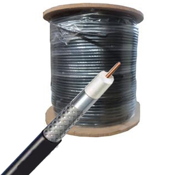 | Polycab Co-Axial Cables Polycab coaxial cable is a type of cable designed for transmitting high-frequency electrical signals, commonly used in cable television (CATV) and... View product → |
Frequently asked questions
What should you do before investigating an LT cable fault?
Identify every supply and backfeed, open the correct disconnectors, apply lockout/tagout, prove the circuit dead with a suitably rated voltage tester, discharge stored energy and prevent re-energisation.
Which instruments help locate an LT cable installation problem?
Use a suitably rated voltage tester for isolation, a continuity tester for conductor paths, an insulation resistance tester for insulation condition and phase-identification tools to confirm conductor identity. Select test voltages and procedures for the cable and equipment ratings.
How do you check whether an LT cable is suitable for an installation?
Compare the cable’s conductor size, voltage rating, insulation type, current capacity, route length, ambient temperature, grouping, installation method and phase or core identification with the design requirements.
What records should accompany an LT cable purchase and handover?
Keep the purchase order, manufacturer and product details, cable size and voltage rating, drum or batch number, delivery inspection, test certificates, installation test results, route records, termination details and approval signatures.
Related products
 | Polycab cable jointing kit A Polycab cable jointing kit is a comprehensive set of components designed for safely and efficiently joining electrical cables, providing... View product → |
 | Polycab Highrise Cables Polycab Highrise Cables are a range of wires and cables specifically designed for use in high-rise buildings, prioritizing safety and performance in... View product → |