A blank, rolling or noisy CCTV image does not prove that the cable has failed. By tracing power, connectors, camera inputs, transmission format, cable specifications and the installed route in order, you can identify the fault and buy a replacement that matches the system.
Key takeaways
- Swap one component at a time before replacing the CCTV cable.
- Match the cable to the camera’s transmission format and impedance.
- Give the dealer length, route conditions, power needs and connector details.
- Test the completed run for picture quality, voltage drop and interference.
Diagnose the fault before replacing the CCTV cable
A swap test isolates the failed part faster than replacing a CCTV cable. Start with a known-good 75 Ω patch lead and a tested power adapter, then change one component at a time.
- Measure voltage at the camera while infrared LEDs are on. A supply that reads correctly with no load can collapse at night; replace it with one matching the camera’s voltage, polarity and current rating.
- Connect the camera directly to the DVR using the short known-good lead. A clear picture points to the installed cable, connector or balun; no picture points to the camera, power or DVR input.
- Move the camera to a known-good DVR channel. If it works there, the original DVR input or its BNC socket is faulty. Test the suspect channel with a known-good camera to confirm.
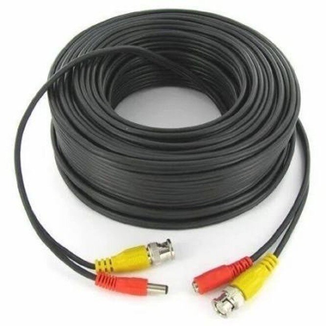
- Inspect and remake each BNC termination. A loose centre pin, braid touching the conductor, corrosion or a poorly crimped plug can cause rolling video, ghosting or a black screen.
- On twisted-pair video, swap the transmitter and receiver baluns individually, then together. A fault that follows one balun identifies that balun; a fault that remains follows the cable or termination.
- Test the installed Polycab camera cable for continuity, shorts, attenuation and interference while lifts, motors or fluorescent lights operate. Confirm the analogue path is 75 Ω end to end, not 50 Ω cable, and check the power pair separately. Replacing cable will not fix a dead camera or DVR input.
Match the cable to the camera’s transmission format
A CVBS, TVI, CVI or AHD camera sends video over a 75-ohm path, so use 75-ohm coaxial cable with compatible BNC connectors, patch leads and DVR input. A 50-ohm RF cable can cause impedance mismatch, ghosting and loss of fine detail.
Keep the camera’s 12 V DC supply on a separate pair unless the system specifically uses another power arrangement.
Cat5e or Cat6 works with an analogue camera only when both ends use video baluns designed for that camera format and resolution. The balun converts the signal for balanced twisted-pair transmission; it does not turn ordinary network cable into an IP link.
Use one matched balun at the camera and another at the DVR, then follow the balun maker’s maximum distance.
An IP camera needs Ethernet from the camera to a network switch, NVR or injector. Use documented Cat5e or Cat6 with RJ45 terminations, and use PoE only when the camera, switch or injector and cable support the required IEEE 802.3af, 802.3at or 802.3bt class.
A Polycab CCTV cable in Mumbai selected for analogue video is not automatically suitable for PoE.
Before buying, match the transmission format rather than asking for a generic camera cable:
- Analogue HD or CVBS: 75-ohm coaxial cable and BNC connectors.
- Analogue camera over twisted pair: Cat5e or Cat6 with matched video baluns.
- IP camera: Cat5e or Cat6 Ethernet, with PoE equipment where required.
Check the specified distance, conductor material, pair arrangement and indoor or outdoor jacket.
Give the dealer a specification brief, not just a product name
A Polycab cable dealer for CCTV signal problems in Mumbai needs a specification brief, not “one CCTV cable.” State the camera format and resolution, maximum route length, connector type, indoor or outdoor location, conduit condition, nearby interference, and whether the cable carries power.
For an analogue HD camera, require a 75 Ω path from camera output through coax, BNC connectors, patch leads and DVR input; 50 Ω RF cable can cause ghosting and lost detail.
| Cable choice | Verify before ordering | Wrong choice causes |
|---|---|---|
| 75 Ω coaxial | Impedance, conductor material and size, shield or braid coverage, attenuation, jacket and BNC compatibility | Reflections, noise or weak detail |
| Solid bare-copper Cat 6 | Category, solid copper conductors, pair layout, jacket rating and RJ45 compatibility | PoE voltage drop, heating or link failure |
| Separate 12 V DC pair | Conductor size, total two-way resistance and route length | Camera rebooting or infrared failure |
Give the dealer this checklist:
- Request the drum label and datasheet showing Polycab manufacturer name, cable designation, category or impedance, conductor material, conductor size, jacket type, fire rating, rated environment, batch or lot number, manufacturing date and marked length.
- Check sequential metre markings, an intact drum, sealed ends and matching batch details on the invoice and test report.
- Identify mains, lift, motor, ballast and variable-frequency-drive routes; request separation or screened construction where rerouting is impossible.
- Ask Prabhat Cables Pvt. Ltd to quote attenuation, DC resistance and test documentation rather than accepting “Polycab camera cable.”
- For PoE, require Ethernet performance documentation; a video coax quote is not a PoE-compliant cable quote.
Related products
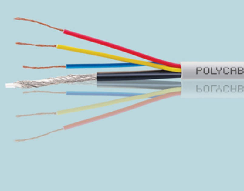 | Polycab CCTV Cables Polycab CCTV cables are specifically designed for use in closed-circuit television (CCTV) systems, offering reliable video signal transmission and... View product → |
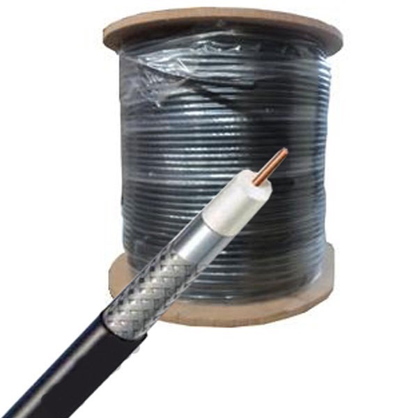 | Polycab Co-Axial Cables Polycab coaxial cable is a type of cable designed for transmitting high-frequency electrical signals, commonly used in cable television (CATV) and... View product → |
Design the Mumbai route around interference, water and heat
Keep CCTV cable away from mains circuits, lift feeders, fluorescent-ballast wiring, motors and variable-frequency-drive cables. A cable category alone will not remove electromagnetic interference; reroute a long parallel section before replacing the camera or recorder.
Use this route plan for Mumbai homes, shops, offices and apartment buildings:
- Run video or Ethernet cable in a separate conduit, tray or riser from power wiring.
- If the routes must cross, cross at 90 degrees and keep the shared distance short.
- Keep cables out of roof heat, direct sun and hot plant-room ducts; use an outdoor, UV-resistant jacket inside suitable conduit.
- Seal conduit entries, junction boxes, glands and BNC joints against rainwater and salt-laden air.
- Provide a drain or sealed route at conduit low points so monsoon water cannot collect around a joint.
- Fire-stop penetrations through apartment walls and floor slabs after pulling the cable.
Do not leave ordinary indoor PVC cable in an exposed shaft, open terrace route or wet underground duct. Water entering one connector can cause intermittent video, corrosion and a fault that appears only during rain.
For a cable between buildings, treat lightning and ground-potential differences as a system problem. Bond and ground surge protection at both ends where required by the installation design; fibre with locally powered media converters avoids a metallic path between buildings.
After installation, test the cable in its final route. Switch nearby equipment on and off, inspect the image or data stream, and measure camera supply voltage under night-mode load.
Calculate the real run and test the installed system
Measure the cable along the actual route, not across the floor plan. Add vertical rises, service loops and patch-panel sections; an unexpectedly long run increases signal attenuation and leaves less margin for connectors and equipment.
Bends do not automatically ruin CCTV, but a tight bend below the cable’s minimum radius can deform the dielectric or conductor. Avoid tightly coiled spare cable beside switches, power supplies or fluorescent fittings.
Each join, patch lead, balun and intermediate amplifier adds insertion loss or an impedance mismatch; a 75 Ω analogue path must remain 75 Ω from camera output to DVR input.
Calculate camera power separately from video distance. For a 12 V camera, voltage drop equals load current multiplied by the power pair’s total two-way resistance.
Measure voltage at the camera while infrared LEDs are on: a camera that works on a short lead can reboot or show dark, noisy images when the long run drops below its operating voltage.
Confirm the repair at the installed route with these checks:
- Inspect BNC or RJ45 terminations for loose pins, braid strands and incorrect pairing.
- Measure voltage at the camera under maximum load.
- For IP cable, run wire-map, length, insertion-loss, return-loss, NEXT and PoE tests.
- For analogue or HD-over-coax, check attenuation, termination quality and interference while nearby equipment switches on.
- View recorded footage at the required resolution and night mode; a live picture alone does not prove stable operation.
Frequently asked questions
How can you diagnose a CCTV signal fault before replacing the cable?
Use a known-good 75 Ω patch lead and a tested power adapter, then replace one component at a time to isolate the failure.
How do you choose a CCTV cable for the camera’s transmission format?
Identify whether the system uses coaxial video, twisted-pair transmission or network Ethernet, then match the cable, impedance and connectors to that format.
What information should you give a CCTV cable dealer?
Provide the camera format, total route length, connector type, power requirements, installation environment and exposure to interference, water or heat.
How should you plan a CCTV cable route in Mumbai?
Measure the complete route, keep signal cable away from high-voltage wiring, protect outdoor sections from water and heat, and test the installed system.